How to Replace an HVAC Valve Core with a Valve-Core Removal Tool
guides 2026-08-03

How to Replace an HVAC Valve Core with a Valve-Core Removal Tool

Diagnose a leaking service port, remove the damaged valve core with an isolation tool, install the correct replacement, and verify a leak-free repair.
HVAC Service Guide

Diagnose a leaking service port, remove the damaged valve core with an isolation tool, install the correct replacement, and verify a leak-free repair.

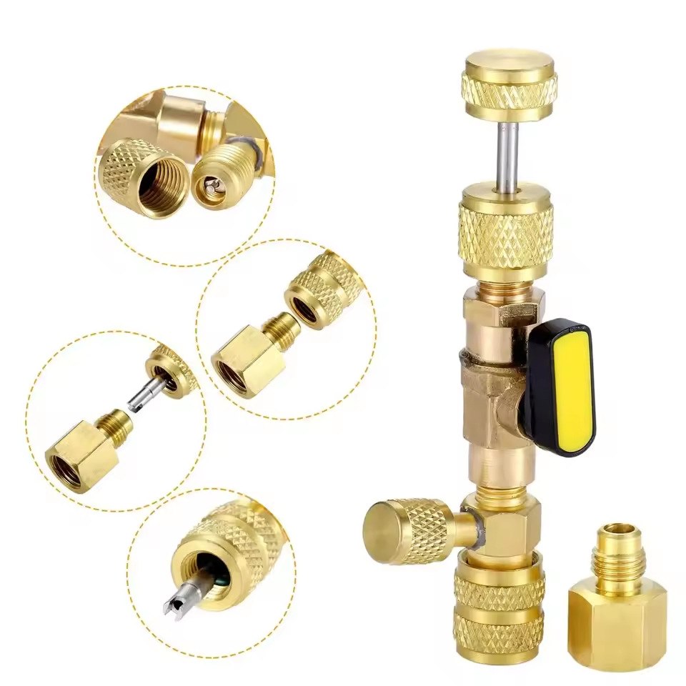
HVAC valve-core removal tool with 5/16-inch adapter
A straight-through valve-core removal tool with an isolation ball valve and adapter.
Safety firstRefrigeration systems may contain high-pressure, toxic, flammable, or oxygen-displacing refrigerants. Wear appropriate eye and hand protection, provide ventilation, control ignition sources where applicable, and follow the equipment and tool manufacturers’ instructions. In the United States, technicians who service equipment that could release regulated refrigerants generally require EPA Section 608 certification. Do not intentionally vent refrigerant; use approved recovery equipment whenever recovery is required.

What the Tool Does

A leaking service-port valve core can cause gradual refrigerant loss, poor performance, and repeat service calls. A valve-core removal tool creates a temporary, controllable service chamber between the HVAC system and the technician. Its driver loosens the core, the pull stem retracts it behind an isolation ball valve, and the ball valve closes before the rear cap is opened.

This design can minimize refrigerant loss when correctly used, but it does not replace system-specific safety checks, refrigerant recovery requirements, or the instructions supplied with the tool.
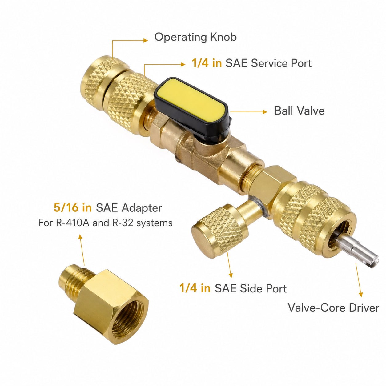
Labeled components of an HVAC valve-core removal tool
Key connections and controls, including the service port, side port, ball valve, driver and 5/16 in SAE adapter.

Main Components

  • Operating knob: Rotates the driver to loosen or install the core.
  • Valve-core driver: Engages the top of the removable valve core.
  • Pull stem: Moves the driver and core through the tool.
  • Ball-valve lever: Opens the stem passage and isolates the system before the rear chamber is opened.
  • Rear cap: Retains the pull-stem assembly. Open only after isolation and safe handling of trapped pressure.
  • Side port: May support measurement, evacuation, or controlled recovery if allowed by the tool manufacturer.
  • Adapter: Changes the connection size when both the tool and HVAC system are compatible.
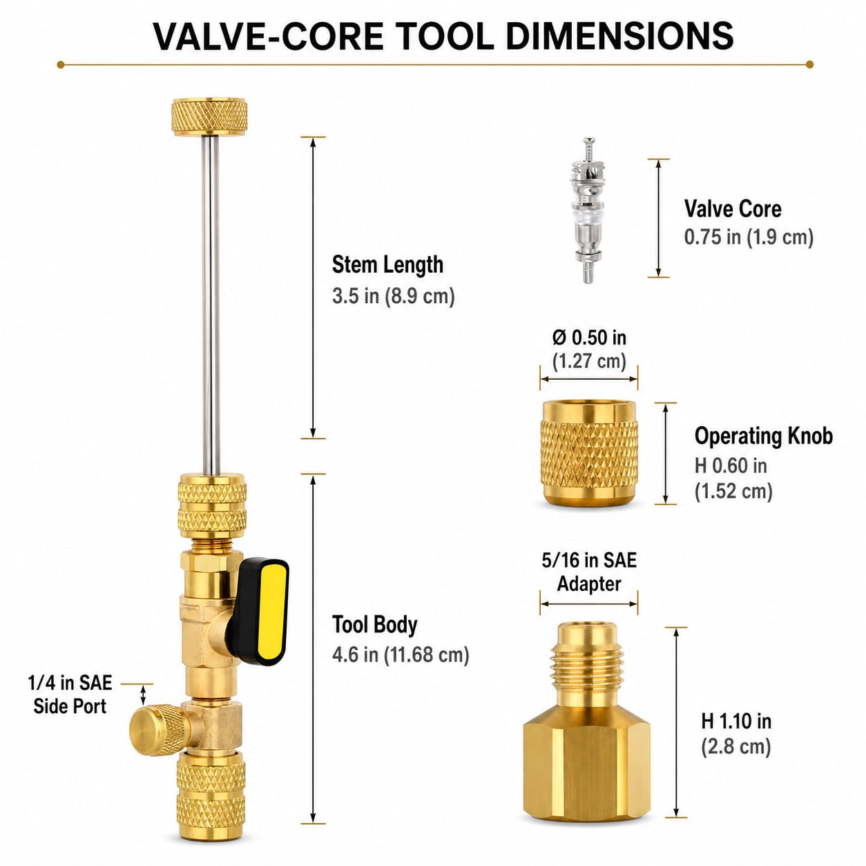
Dimensions of a valve-core removal tool, valve core, operating knob and adapter
Confirm actual dimensions and pressure ratings against the seller’s specification before use.

Before You Begin

  1. Identify the refrigerant and expected service pressure.
  2. Confirm that the tool, seals, hoses, gauges and adapter are rated for that refrigerant and pressure.
  3. Verify the service-port size. Never force mismatched 1/4 in and 5/16 in SAE fittings.
  4. Select a replacement core that matches the port, refrigerant, temperature range and pressure requirements.
  5. Inspect the driver tip, O-rings, threads and ball valve for dirt or damage.
  6. Electrically isolate the equipment when required by the manufacturer’s service procedure.
  7. Prepare compliant recovery equipment for any refrigerant that must be removed.
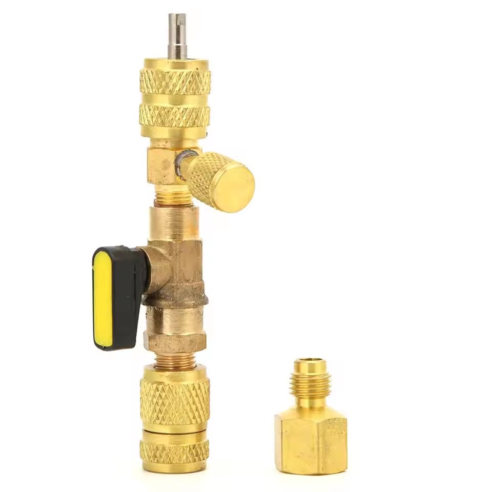
Close-up details of the tool adapter, driver and threaded connections
Inspect the adapter, threads, seals and driver before attaching the tool.

Confirm That the Valve Core Is Leaking

Do not replace the core based only on low system pressure. Clean the service port and inspect the cap, cap gasket and port body. Test with an approved electronic leak detector or bubble solution suitable for the refrigerant.

Bubbles at the center of the core may indicate a loose, contaminated or damaged valve core. Leakage around the port body, joint, flare or cap threads points to a different repair.

Valve-Core Removal Procedure

The sequence below describes the common operating principle of a straight-through removal tool. Always defer to the instructions supplied with your exact tool and equipment.
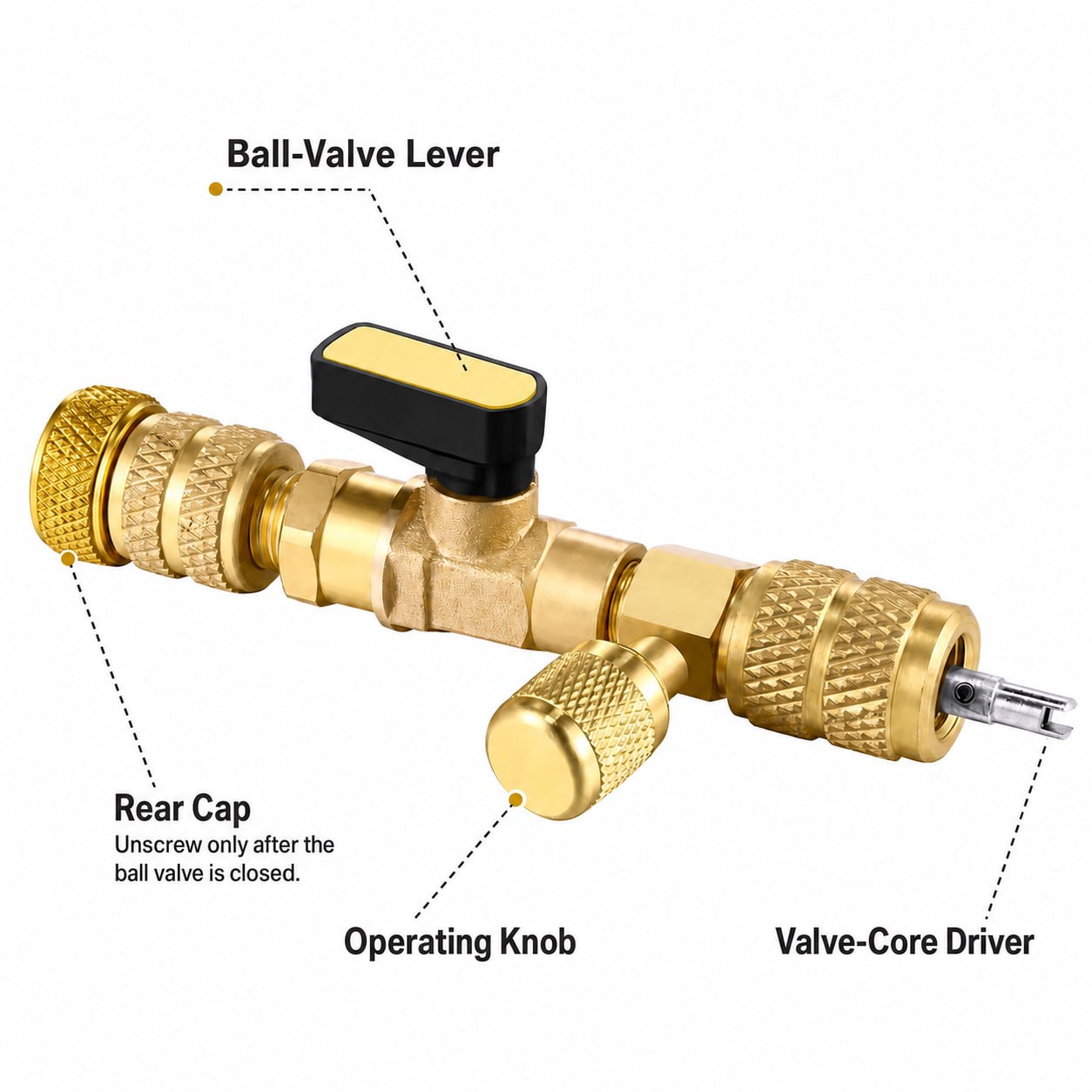
Operating knob, rear cap, ball-valve lever and valve-core driver
Do not open the rear cap until the removed core is behind the closed ball valve.

1. Prepare and connect the tool

Retract the driver stem fully. Set the ball valve to the open position so the stem can pass through the tool. Attach the correct fitting or approved adapter, then connect the tool squarely to the service port. Tighten only enough to create a secure seal.

2. Engage and loosen the core

Advance the stem until the driver engages the valve core. Maintain light inward pressure and rotate the operating knob counterclockwise. Stop if the driver slips, binds or will not remain aligned; forcing it can damage the core or service-port threads.

3. Retract the core and isolate the system

After the core is fully unthreaded, pull the stem completely back until the core is safely behind the ball valve. Only then close the ball valve to isolate the refrigerant side of the system.

4. Handle trapped pressure and remove the core

The rear chamber may retain a small amount of refrigerant. Keep your face and hands away from the opening and use the tool’s approved recovery or pressure-handling method. If the side port is intended for recovery, connect it to suitable recovery equipment before opening the chamber. Once safe, unscrew the rear cap and withdraw the stem with the removed core.
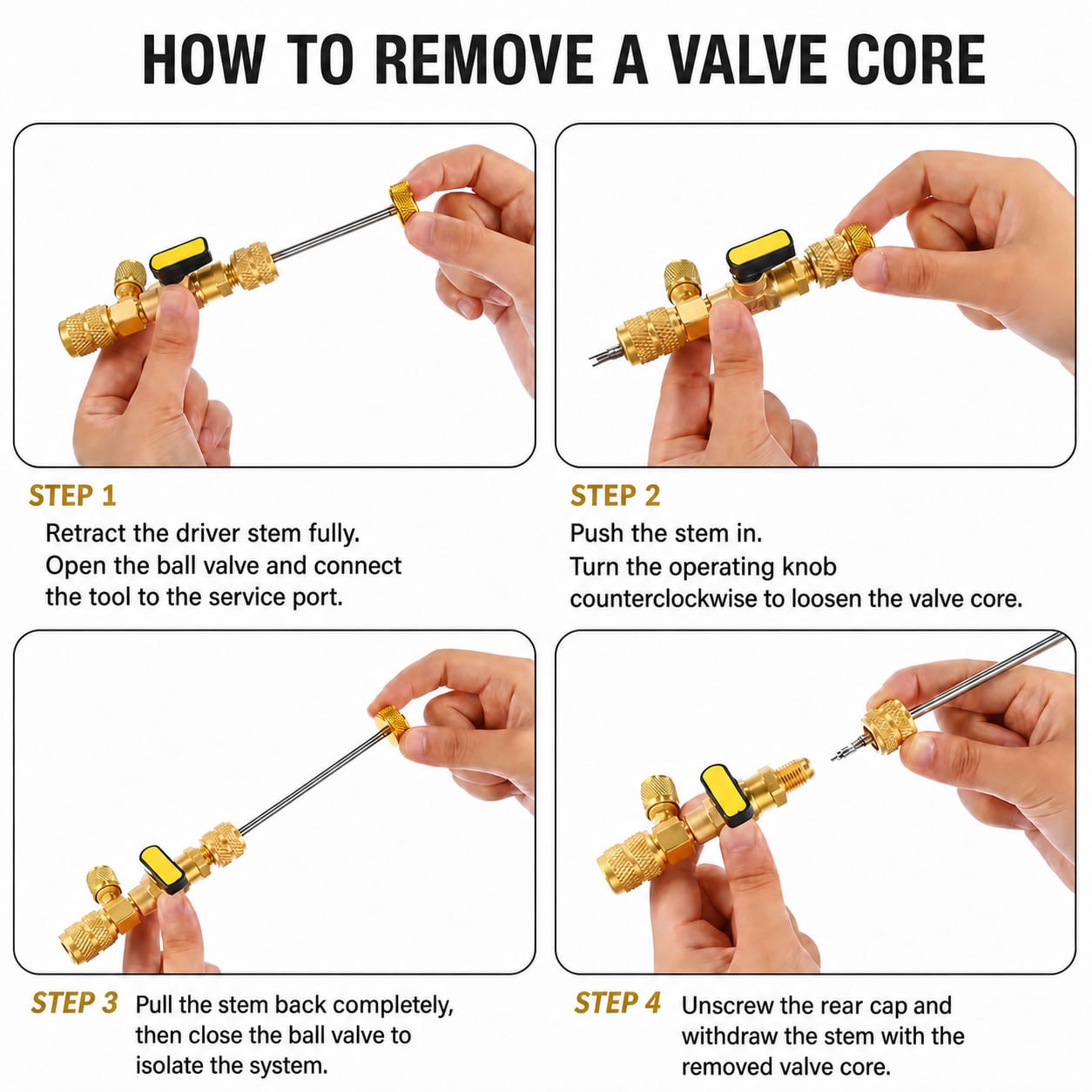
Four-step HVAC valve-core removal procedure
Open the ball valve before advancing the stem; close it only after the removed core has been retracted behind the valve.

Install the Replacement Valve Core

  1. Inspect the removed core and driver. Prevent dirt, oil, thread sealant and metal particles from entering the port.
  2. Fit the correct replacement core securely onto the driver.
  3. Reinsert the pull-stem assembly and tighten the rear cap while the ball valve remains closed.
  4. Open the ball valve slowly and check for abnormal leakage or movement.
  5. Advance the stem until the new core enters the service-port threads.
  6. Rotate the knob clockwise and tighten to the equipment or valve-core manufacturer’s specification. Do not overtighten.
  7. Retract the driver completely and disconnect the tool according to its instructions.
  8. Install a clean service-port cap with an intact gasket; the cap is an important secondary seal.
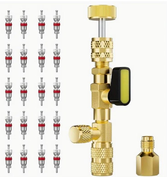
Valve-core removal tool beside multiple replacement valve cores
Use only valve cores approved for the port, refrigerant, temperature and pressure range.

Leak-Test and Verify the Repair

Retest the center of the new core, service-port body, adapter joint and cap seal with an approved leak detector or bubble solution. Confirm that system pressure and operation match the current operating conditions. If refrigerant was recovered or the charge was disturbed, follow the equipment manufacturer’s charging method rather than charging by pressure alone.

Common Problems and Corrections

ProblemLikely causeRecommended action
Driver will not engageWrong driver, poor alignment or damaged core headStop, retract the stem, confirm compatibility and realign without force.
Stem will not retractCore is not fully unthreaded or the driver is bindingRe-engage carefully and continue loosening; never pull with excessive force.
Rear cap is difficult to openBall valve is open or the chamber remains pressurizedStop, verify isolation and handle trapped refrigerant by the approved method.
New core still leaksIncorrect core, damaged seal or seat, debris, or improper tighteningRecover refrigerant if necessary, inspect the seat and install the correct core.
Leak remains elsewhereDamaged port body, joint, flare or service capRepair the actual leak source and replace the cap gasket if required.
Final takeaway: The safe sequence is simple but critical: open the ball valve before advancing the stem, retract the removed core completely, close the ball valve before opening the rear chamber, then leak-test the completed repair.

Regulatory References

← Назад к новостям